LMS 10000
Diesel Electric
Locomotive
or
Why I joined the LMSCA by Derek Payne
Diesel Electric
Locomotive
or
Why I joined the LMSCA by Derek Payne
I recently joined the LMS Carriage Association (LMSCA) as a result of a question asked by a friend some five years ago. The question:- “Why not build a model of LMS 10000 and 10001”?
It sounded simple, well at least to my friend, for I had built numerous models of diesel locomotive over the years. I build bespoke models of historic locomotives for 7¼" gauge, which equates to just over 1/8 of a full sized engine, so the model of 10000 turns out at 7 feet 10 inches long.
My friend’s thought was that having built steam locomotives in the past, then building a model diesel was simple, “it is just a box on wheels”. To his surprise, and four years later, he has now had to eat his words! For me the “fun” begins with researching the original to gain sufficient information with which to draw out the model and all the components necessary to ensure that in all visible areas the model looks like the original “real thing”. The areas that are hidden are engineered in a no- prototypical fashion since it is not possible to replicate a working diesel engine, generator and control system based on the full sized original, and recourse must be made to battery electric traction for the model.
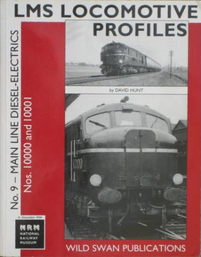
By a stroke of good fortune, a couple of months after the project started a new book published in conjunction with the NRM became available and it contained a full history of the two locomotives with numerous photographs and copies of works drawings. Suffice to say, this saved a huge amount of time in the research and design phase and removed the need to visit the NRM at York to search through the drawing files. Additional information was obtained from the LMS Society, particularly details of the works plates and body side lettering for 10000. In building the model I spent around a total of nine months calculating dimensions and making 70 drawings of the components and assemblies.
The design of the models and their manufacture involved using a variety of processes including CNC turning and metal forming, laser cutting, aluminium sand castings, investment (lost wax) castings, glass fibre mouldings and plastic moulding. The last four processes required patterns or moulds to be made for each part, so and it became
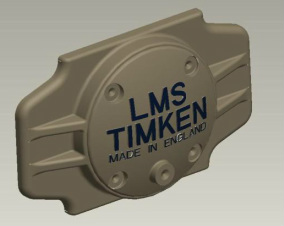
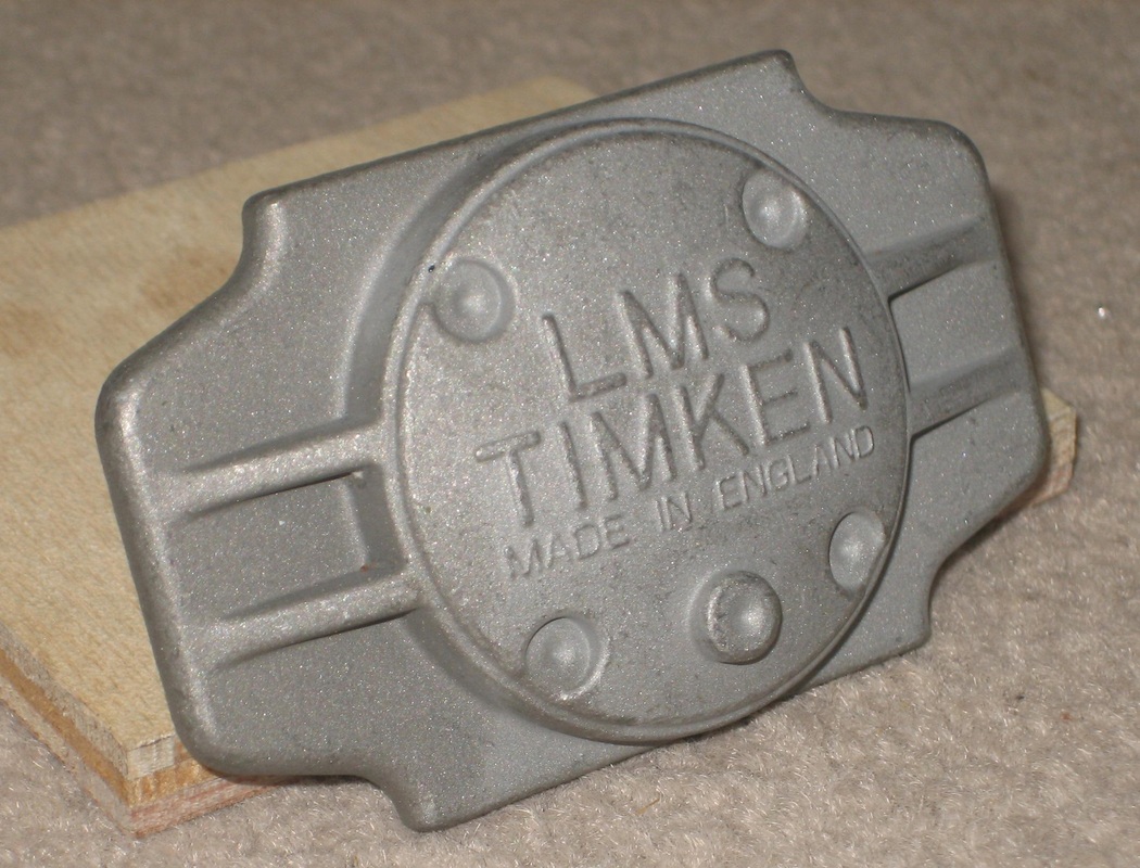
a good test of our design, woodworking and machining skills. One part, the Timken Axle-box cover required a specialised technique of 5-axis CNC machining to produce the Lettering on the spherical surface of the cover and this is seen in the picture of the wax moulding and steel component.
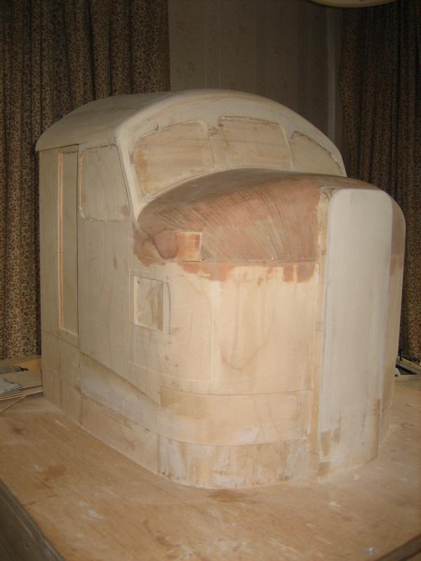
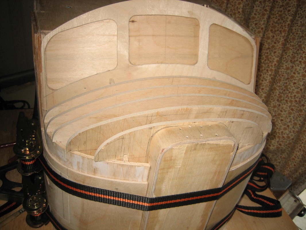
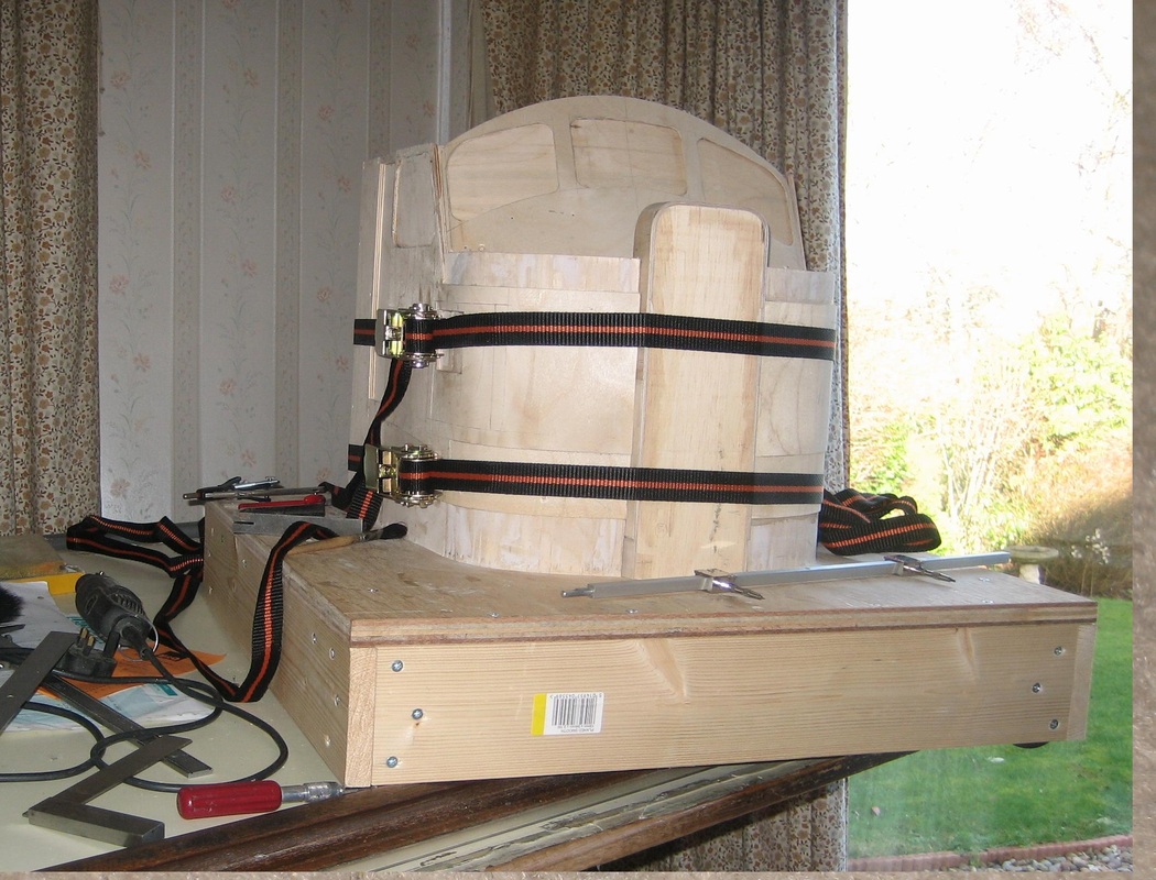
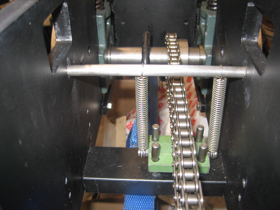
The main body and chassis of the locomotive is made from steel including the curved roof. The cab exteriors are made from fibreglass mouldings. Buffers are steel investment castings as are the spring plates on the bogies and the axle-box covers. The body side grilles are made of individual steel slats or machined brass plates, and windows are acrylic sheet. Bogies have internal steel frames and axle bearings with chain drive to all wheels. The side frames, purely decorative are aluminium castings and steel fabrications with detailed, non-functioning, brake gear. The “LMS” letters and Works Plates are based on photographs of the originals, kindly supplied by the“LMS Society”. The Lettering, numbers and side strips are made of aluminium like the original locomotive, and the works plates are photo etched into nickel silver. The mould for the cab is made from a wooden plug shown under construction below. The curved nose was formed using a double planked method of lime then walnut strips over a ply former as often employed in model ship hull construction.
The power is provided by a 750 Watt 24 volt permanent magnet motor on each bogie with a 120 amp controller and four 12 volt 75 Amp-Hour traction batteries arranged in two series pairs connected in parallel. A sound system with 40 Watt (RMS) amplifier and a 4 inch speaker in a bass reflex-box sounds very similar to the original 10000. The control system is arranged to run the locomotive on its own or double-headed with 10001 whilst using a single control box for both locomotives.
The completed 10000 with the batteries installed weighs in at an estimated 375 kgs/826 lbs.
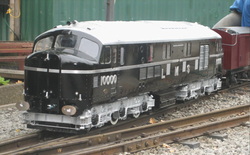
As with all scale models, the “devil” is in the details which have taken many months to make and complete and are located throughout the locomotive exterior and the interiors of the cabs. The results of this work are well worth it, as the photograph of the completed 10000 shows. This coming winter should see the completion of the twin locomotive 10001, and the two engines will then run coupled together as they ran in the early 1950’s on the West Coast Main Line in command of the up Royal Scot and the down Night Sleeper.
So why did this lead to my joining the LMSCA? Having completed the locomotives, they need some things to pull to represent a train, and to accommodate seated passengers. Having made detailed replicas of the locomotives, we decided that only detailed replicas of contemporary coaches would suffice. So looking through the books again we decided that LMS Stanier period III coaches would fit the bill. We could also have used BR Mk1 coaches which are available as commercial models, but the locomotives were a LMS design and so we believed they would look best
with LMS coaches, also, the commercial coaches compromised on scale length and level of detail.
At the scale of the models, a 12-14 coach train would be far too long for the stations on most miniature railways, and so we will limit our train to represent the Edinburgh portion of the Royal Scot between 1948 and 1951. We will be taking some licence on this since I do not find the BR carmine and cream (blood and custard) of early BR to be attractive, and certainly not representative of the LMS, and so our train will be in LMS maroon with the simple lining and LMS lettering and numbers.
The model coaches must match the engines in the level of detailed exteriors and interiors, and so whilst the books on the coaches are most useful, it is necessary to get up close to a full sized coach to obtain accurate sizes and details. Thus, needing a good source of information and access to LMS coaches I contacted Derek Mason of the LMSCA and was well received, and then I visited Wirksworth to measure and photograph the superbly restored 27162. I had a most enjoyable day which I concluded by my completing my membership application. With the information gain I began the drawing of the bogie, under-frame and body of the coaches to be modelled.
A subsequent exchange of emails with LMSCA member Derek Winter followed, in which he suggested I consider modelling LMS 1037, a period III rebuild in 1932 of a period two semi Restaurant First Open to diagram D1719. Drawing has started on this interesting vehicle which replaced the period two coach to the same diagram that was destroyed in the Leighton Buzzard crash of 1931.
As much as I would wished to build a LMS 12 wheeled dining Car, this type was not used in the Royal Scot of this era, and so I have selected a 50ft Kitchen car to D1912 together with a Third Open to D1999. At the ends of the train will be a Corridor Brake Third to D1968 and a Corridor Brake First to D1910, although, this could change slightly as I gain more knowledge of the coaches used in the Royal Scot train.
As progress is made on these models, I hope to keep members up to date with progress and pictures. Doubtless the models will use some of the techniques and processes we employed on the locomotives 10000 and 10001, and certainly some other techniques since the coach interiors will be mainly made from wood.
References LMS Locomotive Profiles No 9 Mainline Diesel-Electrics 10000 & 10001
published by Wild Swan ISBN 1 905184 04 2
The Illustrated History of LMS Standard Coaching Stock by David Jenkinson and Bob Essery
published by OPC ISBN 0 86093 451 9
It sounded simple, well at least to my friend, for I had built numerous models of diesel locomotive over the years. I build bespoke models of historic locomotives for 7¼" gauge, which equates to just over 1/8 of a full sized engine, so the model of 10000 turns out at 7 feet 10 inches long.
My friend’s thought was that having built steam locomotives in the past, then building a model diesel was simple, “it is just a box on wheels”. To his surprise, and four years later, he has now had to eat his words! For me the “fun” begins with researching the original to gain sufficient information with which to draw out the model and all the components necessary to ensure that in all visible areas the model looks like the original “real thing”. The areas that are hidden are engineered in a no- prototypical fashion since it is not possible to replicate a working diesel engine, generator and control system based on the full sized original, and recourse must be made to battery electric traction for the model.
By a stroke of good fortune, a couple of months after the project started a new book published in conjunction with the NRM became available and it contained a full history of the two locomotives with numerous photographs and copies of works drawings. Suffice to say, this saved a huge amount of time in the research and design phase and removed the need to visit the NRM at York to search through the drawing files. Additional information was obtained from the LMS Society, particularly details of the works plates and body side lettering for 10000. In building the model I spent around a total of nine months calculating dimensions and making 70 drawings of the components and assemblies.
The design of the models and their manufacture involved using a variety of processes including CNC turning and metal forming, laser cutting, aluminium sand castings, investment (lost wax) castings, glass fibre mouldings and plastic moulding. The last four processes required patterns or moulds to be made for each part, so and it became
a good test of our design, woodworking and machining skills. One part, the Timken Axle-box cover required a specialised technique of 5-axis CNC machining to produce the Lettering on the spherical surface of the cover and this is seen in the picture of the wax moulding and steel component.
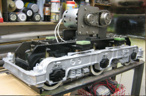
The main body and chassis of the locomotive is made from steel including the curved roof. The cab exteriors are made from fibreglass mouldings. Buffers are steel investment castings as are the spring plates on the bogies and the axle-box covers. The body side grilles are made of individual steel slats or machined brass plates, and windows are acrylic sheet. Bogies have internal steel frames and axle bearings with chain drive to all wheels. The side frames, purely decorative are aluminium castings and steel fabrications with detailed, non-functioning, brake gear. The “LMS” letters and Works Plates are based on photographs of the originals, kindly supplied by the“LMS Society”. The Lettering, numbers and side strips are made of aluminium like the original locomotive, and the works plates are photo etched into nickel silver. The mould for the cab is made from a wooden plug shown under construction below. The curved nose was formed using a double planked method of lime then walnut strips over a ply former as often employed in model ship hull construction.
The power is provided by a 750 Watt 24 volt permanent magnet motor on each bogie with a 120 amp controller and four 12 volt 75 Amp-Hour traction batteries arranged in two series pairs connected in parallel. A sound system with 40 Watt (RMS) amplifier and a 4 inch speaker in a bass reflex-box sounds very similar to the original 10000. The control system is arranged to run the locomotive on its own or double-headed with 10001 whilst using a single control box for both locomotives.
The completed 10000 with the batteries installed weighs in at an estimated 375 kgs/826 lbs.
As with all scale models, the “devil” is in the details which have taken many months to make and complete and are located throughout the locomotive exterior and the interiors of the cabs. The results of this work are well worth it, as the photograph of the completed 10000 shows. This coming winter should see the completion of the twin locomotive 10001, and the two engines will then run coupled together as they ran in the early 1950’s on the West Coast Main Line in command of the up Royal Scot and the down Night Sleeper.
So why did this lead to my joining the LMSCA? Having completed the locomotives, they need some things to pull to represent a train, and to accommodate seated passengers. Having made detailed replicas of the locomotives, we decided that only detailed replicas of contemporary coaches would suffice. So looking through the books again we decided that LMS Stanier period III coaches would fit the bill. We could also have used BR Mk1 coaches which are available as commercial models, but the locomotives were a LMS design and so we believed they would look best
with LMS coaches, also, the commercial coaches compromised on scale length and level of detail.
At the scale of the models, a 12-14 coach train would be far too long for the stations on most miniature railways, and so we will limit our train to represent the Edinburgh portion of the Royal Scot between 1948 and 1951. We will be taking some licence on this since I do not find the BR carmine and cream (blood and custard) of early BR to be attractive, and certainly not representative of the LMS, and so our train will be in LMS maroon with the simple lining and LMS lettering and numbers.
The model coaches must match the engines in the level of detailed exteriors and interiors, and so whilst the books on the coaches are most useful, it is necessary to get up close to a full sized coach to obtain accurate sizes and details. Thus, needing a good source of information and access to LMS coaches I contacted Derek Mason of the LMSCA and was well received, and then I visited Wirksworth to measure and photograph the superbly restored 27162. I had a most enjoyable day which I concluded by my completing my membership application. With the information gain I began the drawing of the bogie, under-frame and body of the coaches to be modelled.
A subsequent exchange of emails with LMSCA member Derek Winter followed, in which he suggested I consider modelling LMS 1037, a period III rebuild in 1932 of a period two semi Restaurant First Open to diagram D1719. Drawing has started on this interesting vehicle which replaced the period two coach to the same diagram that was destroyed in the Leighton Buzzard crash of 1931.
As much as I would wished to build a LMS 12 wheeled dining Car, this type was not used in the Royal Scot of this era, and so I have selected a 50ft Kitchen car to D1912 together with a Third Open to D1999. At the ends of the train will be a Corridor Brake Third to D1968 and a Corridor Brake First to D1910, although, this could change slightly as I gain more knowledge of the coaches used in the Royal Scot train.
As progress is made on these models, I hope to keep members up to date with progress and pictures. Doubtless the models will use some of the techniques and processes we employed on the locomotives 10000 and 10001, and certainly some other techniques since the coach interiors will be mainly made from wood.
References LMS Locomotive Profiles No 9 Mainline Diesel-Electrics 10000 & 10001
published by Wild Swan ISBN 1 905184 04 2
The Illustrated History of LMS Standard Coaching Stock by David Jenkinson and Bob Essery
published by OPC ISBN 0 86093 451 9
|
|
|
|
|
|
|
|
