Electrical Control
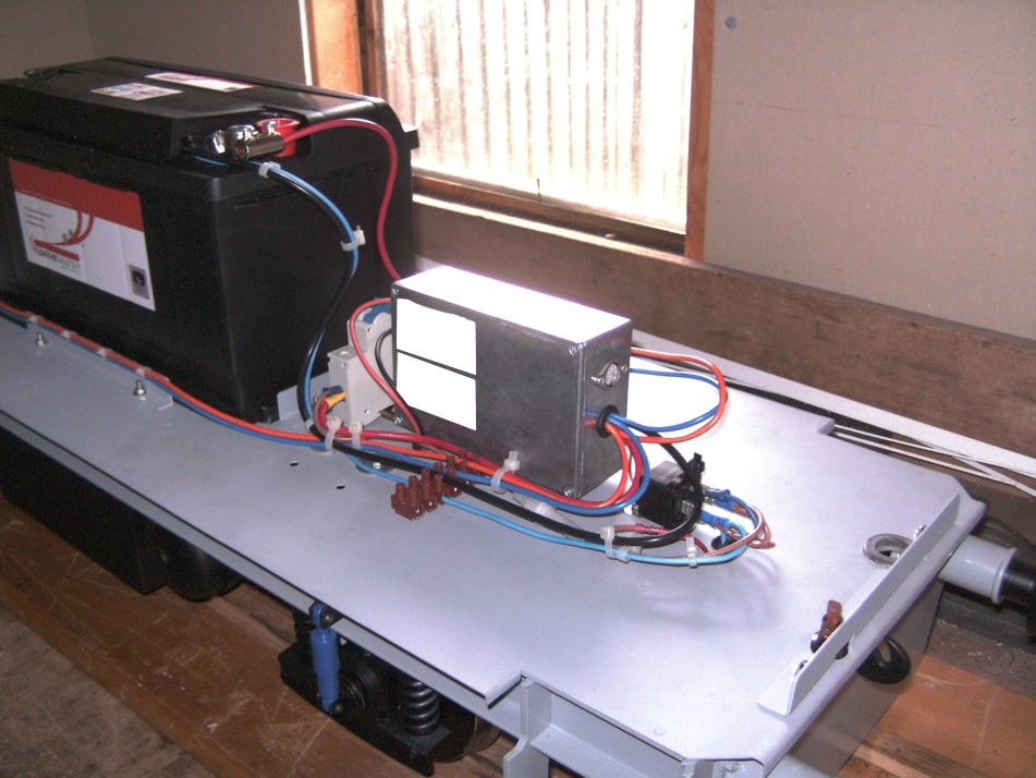
The correct term for most model locomotives is a 'Storage Battery Locomotive'. The power supply is generally by 12 volt Lead Acid batteries. One battery will provide 12 volts. Two batteries may be connected in series to provide a 24 volt supply to the traction motors.
Connected between the power supply and the traction motors is a control system.
The heart of the system is a 'Black Box' (silver box in the picture) containing the electronic control which is beyond description on this page. A number of wires exit the box for the model engineer to connect to the motors, handset, horn and any ancillaries such as sound units and lights.
The Handset shown in the photograph is connected to the Black Box using a DIN plug and has a keyswitch, horn button, forward/neutral/reverse toggle switch, and a centre sprung joystick for power and braking.
When a locomotive is being moved on the track by towing/pushing then the Direct Current motors are rotating and can act as generators. Any feedback into the electronics can be damaging to the components and should be avoided. The motors can be isolated from the control circuit by including a normally-open relay into the motor leads. The relay can be activated by a manual switch or by a signal from the controller when power is applied to the circuit.
The description on this page only provides an overview of electrical control and the manufacturers instructions should be followed for all installations.